This posting describes the calibration of the SM200C (signalhound3) high-band chain, as built in the 2024-25 season. It should contain all the information you need to understand and predict SM200C measurements of RF sources above ~1GHz.
Calibration
The goal is to establish what value the SM200C measures in dBm for a given incident irradiance in dBW/m2 ("dB Watts per Square Meter").
All calculations for the calibration are in the attached Jupyter notebook.
Estimating the gain of the RF chain
First, we need to establish the gain of the RF chain, from the antenna port to the SM200C input port.
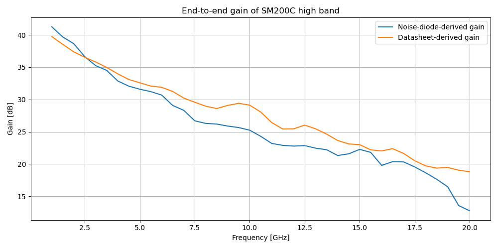
Estimated gain from datasheet values
Reading off the system diagram and corresponding datasheets (see below), we can estimate the gain of the full system by simply summing the datasheet attenuation or gain values for each component in the signal chain.
The datasheet values are recorded in this attached JSON file, and summed in the 3rd cell of the attatched notebook.
First convert from excess noise ratio to noise temperature: 24dB ENR = 251.2 linear ENR, and $\text{ENR} = (T_{on}-T_0)/T_0$, for $T_0$ the ambient temperature (290K), so $T_{on} \simeq 7.3e4~\text{K}$.
Then, we use $P = k_B T B$ to compute the power applied to the front of the RF chain, and compare with the power recorded by the SM200C to find the gain.
Gain of the SM200C high band RF chain
While we're here, we can also estimate the temperature of the SM200C system as a whole, following eqn 1-6 through 1-8 from this HP reference document.
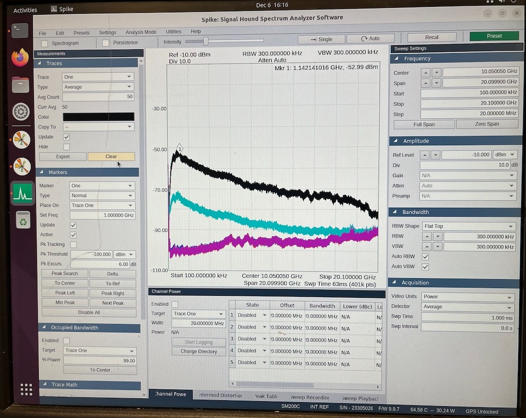
We use the NS-on and NS-off data points as hot and cold measurements to calculate the Y factor as $Y = P_{on}/P_{off} = -73\text{dBm}/-90\text{dBm} \simeq 50$.
Then, we can compute the noise temperature $T_{sys} = T_{on}-Y\frac{T_{off}}{Y-1} \simeq 1200K$, or a noise figure of 7.1dB.
This seems reasonable for a high gain, room temperature system.
Antenna
We also need to compute the effective aperture of the antenna, which varies with frequency.
The effective aperture is (Kraus eqn 6-16) $A_e = G \lambda^2/(4\pi)$, for G the linear gain of the antenna (in this case, 1.26, from the datasheet).
This is computed in cell 5 of the attached notebook.
Note that this is a shortcut - the by-the-book method would be to use the antenna factor and impedance, rather than gain.
However, antenna factors are in voltage units, and would ultimately get us a sensitivity in field units (V/m) instead of power units.
The method I use here should be good to within a dB or two.
End-to-end calibration
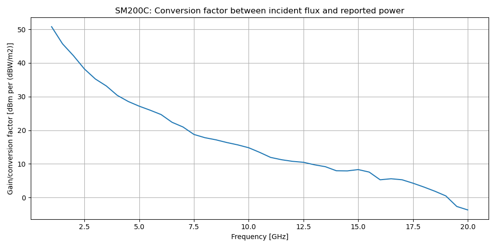
Finally, we can assemble the full calibration:
$$
\text{Measured power [dBm]}
=
\text{Incident irradiance [dBW/m}^2]
+
\underbrace{10\log_{10}(A_e) + \text{Gain} + 10\log_{10}(1\text{W}/1\text{mW})}_{\text{"Conversion Factor"}}
$$
Conversion factor between measured power and incident irradiance
These data are included as a csv file for future use.
To convert from SM200C-measured values to incident flux, just subtract the conversion factor at the appropriate frequency from the measured dBm.
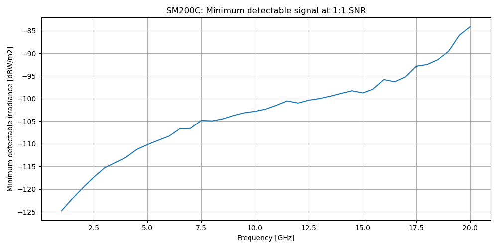
This results in the following minimum detectable power (i.e. SNR=1) at our monitoring bandwidth of 1MHz:
Comparing with Alex Pollack's 2022/23 Starlink data
In 2022-23, Alex Pollack (SPT winterover) took measurements of a Starlink terminal using an Anritsu spectrum analyzer, two LNAs, and a ~11dBi horn.
The tests are recorded in this atttached document.
We can use these test data to estimate the Effective Isotropic Radiated Power (EIRP) of a Starlink terminal pointed into the dark sector.
This section also serves as a worked example of how to use the calibration data.
Alex recorded the Starlink terminal with no mitigation at -40dBm.
Using datasheet values from the documented components, I find that the end-to-end gain of the RF chain Alex used here was ~43dB, plus an 11dBi antenna.
The free space path loss between DSL and the RF building (~1800m) at 14.5GHz is ~ -120dB.
So, the Starlink terminal's EIRP was [measured power] - [Anritsu setup gains] - [FSPL] ~= 32.6dBm.
Finally, we can use this EIRP value to figure out what we expect to see see on the SM200C if we measured the same Starlink setup.
We reuse the terminal EIRP and FSPL values, but use the SM200C RF chain and antenna gains instead:
$$P_\text{meas, SM200C} = \text{(Term. EIRP)} + \text{[SM200C gains]} + \text{FSPL} = 32.6 \text{dBm} + 21.6 \text{dB} + 1\text{dBi} - 120.6\text{dB}$$
predicting a measured power of -65.4dBm.
The 21.6 dB is for the antenna chain, and may be read off Figure 1 or the attached notebook, and the 1 dBi is from the (omnidirectional) antenna datasheet.
Comparing this value to the Cyan trace on the screenshot below, it looks like we would see it ~33dB above the noise floor with the current Signalhound setup.
Based on Alex's measurements and the above calculations, I predict that we should be able to see a Starlink terminal at the RF building with the SM200C at DSL.
It's confusing that we did not see anything from the Starlink firmware update performed on 04 Nov 2025, though that may have just been because the update was mostly downlink, with not much data uploaded.
There are a couple of options if we require additional gain.
The best and easiest option is to switch from examining max-hold data to mean data, allowing us to drive down the noise floor by averaging.
The other options are to narrow the sweep to a ~1GHz range around the Starlink band and/or use a directional antenna, each of which would increase our sensitivity to Starlink but significantly degrade the SM200C as a general monitoring instrument.
Reference documents
Calibration trace
Magenta: amps off; Cyan: amps on, noise off; Black: amps on, noise on.